|
| |
TM 5-4210-220-12
4-18. PUMP, PIPING, AND VALVES-Continued
4-18.11 Air Actuated Ball Valves.
This task covers
a.
Removal
b.
Installation
c.
Adjustment
TOOLS
Shop Equipment, Automotive
Maintenance and Repair,
NSN 4910-00-754-0705
EQUIPMENT CONDITION
All Piping Drained
Foam Tank Drained (see para. 2-13)
Main Engine Shutdown (see para. 2-10)
APU Shutdown (see para. 2-12)
Batteries Disconnected (see para. 4-24)
Pump Body Heat Shield Removed (see para. 4-11.2)
MATERIALS/PARTS
11, Appendix E Electrical Tape
22, Appendix E Pipe Sealant
NOTE
The following is a general remove/install
procedure. To remove/install a specific air
actuating
ball
valve
use
the
following
illustration as a guide. It may be necessary to
remove the actuator prior to ball valve removal.
REMOVAL
(1)
Disable the switching system by setting the cab MODE
switch to mid-position. Tag this switch identifying
'Repairs in Progress'.
(2)
Bleed the air from the actuator by setting the cab
WATER EDUCTOR and FOAM VALVE switch to mid-
position.
(3)
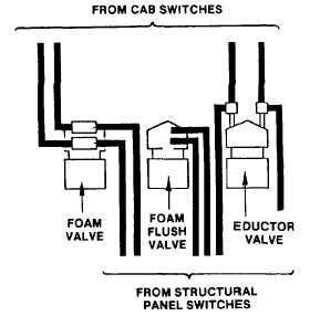
Bleed the structural panel air lines by setting the FOAM
VALVE, WATER EDUCTOR and FLUSH switches to mid-position.
(4)
Tag and remove the air lines from the air actuated ball valve being removed. Tagging will ensure proper
assembly.
NOTE
If only the ball valve is being removed it is acceptable to leave air lines connected and to
suspend the actuator from the frame using mechanics wire.
4-244
|

