|
| |
TM 5-4210-220-12
4-13 PUMP BODY - Continued
4-13.1 Structural Control Panel - Continued
(4)
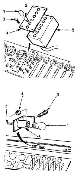
Remove two screws (3) attaching bezel
plate (4) and monitor box (5) to control
panel.
(5)
Remove level monitor from pump body.
(6)
Apply threadlock liquid (item 29, Appendix
E) to screws (3).
(7) Install new monitor box (5) and bezel
plate to control panel using screws (3)
Tighten screws firmly.
(8)
Connect plugs to monitor.
f.
Panel Lamp Repair.
NOTE
Control
panel
may
remain
installed on console. To replace
light bulb, carry out step 1 only.
(1)
Remove bulb (1) Replace if broken or
burned out.
(2)
Disconnect wires (2) inside console.
(3)
Remove screw (3) and nut (4) attaching
lamp socket (5).
(4)
Remove and replace lamp socket.
(5)
Install new lamp socket. Route wires (2)
through panel into console.
(6)
Attach lamp socket to light bar using
screw (3) and nut (4). Tighten screw
firmly.
(7)
Connect lamp wires inside console.
(8)
Install bulb (1).
4-124
|

