|
| |
TM 5-4210-220-12
4-13 PUMP BODY - Continued
d.
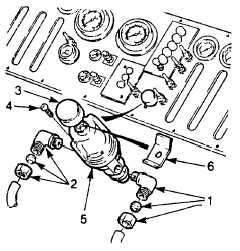
Throttle Regulator Repair.
NOTE
Control panel may remain installed on console.
(1)
Tag and remove air lines and fittings (1 and 2).
(2)
Remove knob (3) and screws (4). If replacing regulator, unscrew locking device (6) and install on new regulator.
(3)
Remove throttle regulator (5) from control panel.
NOTE
The throttle regulator (5) is identical to the air regulator used in the primary brake system.
(4)
Repair regulator as detailed in para. 4-22.6
(5) Apply threadlock liquid (Item 29, Appendix E) to screws (4).
(6)
Install regulator (5) to control panel using screws (4). Tighten screws firmly.
(7)
Install knob (3).
(8)
Connect air lines and fittings (1 and 2) to regulator as tagged. Coat all threads with pipe sealant (Item 22, Appendix
E) prior to installation.
(9)
Set battery switch to BOTH and start main engine. Set cab MODE switch to STRUCT and check engine speed
can be controlled with the regulator.
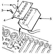
e. Level Monitor Repair.
NOTE
This procedure is applicable to both
foam and water level monitors. The
water
level
monitor
only
is
illustrated.
Control
panel
may
remain installed on console. Neither
foam or water level monitor box, (5)
is repairable. Replace if defective.
To replace light bulbs or lenses,
carry out steps 1 and 2 only. (1)
Unscrew applicable lens
(1) and remove bulb (2).
(2)
Replace bulb and/or lens as required.
Insert bulb in holder and install lens.
(3)
To remove monitor box (5), disconnect
plugs leading to box and tag as necessary.
4-123
|