|
| |
TM 5-4210-220-12
4-13 PUMP BODY - Continued
g.
Winterization System Controls Repair
NOTE
Control
panel
may
remain
installed on console. None of the
winterization
system
control
components
are
repairable.
Faulty
components
must
be
replaced. Refer to applicable
steps below for replacement of
individual components.
(1)
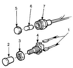
Tag and disconnect winterization heater
switch wires (1).
(2)
Remove knob (2), nut (3), and switch
body (4).
(3)
Install new switch using nut (3) and knob
(2) supplied with switch.
(4)
Connect wires to switch as tagged in step
1.
(5)
Remove indicator lens (5) and bulb (6).
(6)
Replace bulb and reinstall indicator lens.
(7)
To replace complete indicator, tag and
disconnect wires and remove. Indicator
bezel nut (7). Remove indicator from
control panel.
(8)
Install new indicator and connect wires as
tagged in step 7.
(9)
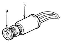
Tag and remove wires from APU switch
(8).
(10)
Remove bezel nut (9) and remove switch
body from control panel.
(11)
Install new switch using bezel nut supplied
with switch.
(12)
Connect wires to APU switch as tagged in
step
9.
NOTE
To access the APU stop control cable, the complete engine must be pulled out of the APU
compartment and reinstalled after the cable is replaced. See para. 4-15.1 for details.
(13)
Disconnect the stop control cable (10) at the APU as required.
4-125
|


