 |
|||
|
|
|||
|
Page Title:
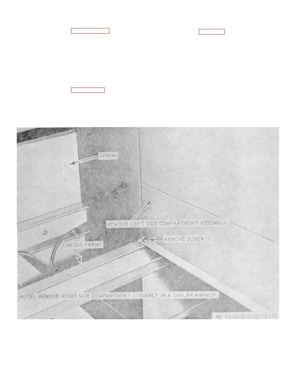
Figure 3-18. Special purpose body compartments, removal and installation. |
|
||
| ||||||||||
|
|
 3-23. Special Purpose Body Compartment
e. Installation.
(1) Refer to figure 3-18 and instatl e left and
lh
b. Removal.
right-hand compartments on the chassis.
(1) Remove ladder support assemblies and
(2) Reverse removal procedure (para 323).
hose beds (TM 5-4210-213-12).
3-24.
Control Panel Testing and Wiring,
Replacement
(2) Remove rear step assembly and apron
(TM 5-4210-213-12).
a. Testing. Refer to wiring diagram (TM 5-4210-
213-12) and test a wire for continuity by disconnecting
(3) Remove water tank assembly (TM 5-
each end from the component or components to which it
4210-213-12).
is connected. With a multimeter set on the ohms scale,
(4) Disconnect and remove rear spotlight
touch the test probe to each end of the wire. If
wiring from compartments.
continuity is not indicated, the wire is defective and must
(5) Refer to figure 3-18 and remove
be repaired or replaced.
compartment assemblies.
b. Replacement. Replace a wire by disconnecting
c. Cleaning. Clean all parts in an approved
it from the component or components and remove the
cleaning solvent and dry thoroughly.
wire. Install a new wire and
d. Inspection and Repair. Inspect all parts for
wear, defects, and damage. Replace or repair worn,
defective, or damaged parts as necessary.
Figure 3-18. Special purpose body compartments, removal and installation.
3-39
|
|
Privacy Statement - Press Release - Copyright Information. - Contact Us |