 |
|||
|
|
|||
|
Page Title:
Figure 64. Foam tank, vent hose, and foam tank, removal and installation. |
|
||
| ||||||||||
|
|
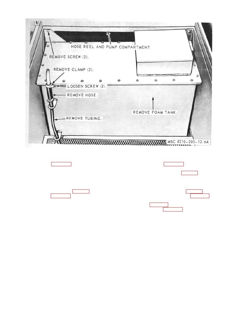 Figure 64. Foam tank, vent hose, and foam tank, removal and installation.
c.
Installation.
f.
Adjustment.
(1) Refer to figure 64, and install the foam
(1) Refer to figure 62, and adjust the pump
tank and vent hose on the compartment.
clutch linkage.
(2) Fill the foam tank (para. 18).
(2) Install the tool box (TM 9-2320-235-20).
128. Water Tank and Lines
127. Foam Tank Strainer, Foam Tank and Vent Hose
a. Removal
a. Removal.
(1) Drain the water tank (para. 20).
(1) Drain the foam tank (para. 20).
(2) Remove the foam tank (para. 127).
(2) Refer to figure 64, and remove the foam
(3) Remove the ladder support assemblies
tank and vent hose from the compartment.
b. Cleaning, Inspection, and Repair.
(4) Refer to figure 65, and remove the water
(1) Clean all parts with a clean cloth
tank from the special purpose body.
dampened in an approved cleaning
b. Cleaning, Inspection, and Repair.
solvent, and dry thoroughly.
(1) Clean all parts with an approved cleaning
(2) Inspect all parts for damaged or defective
solvent, and dry thoroughly.
condition.
(2) Inspect all parts for damaged or defective
(3) Replace or repair damaged or defective
condition.
parts as necessary.
(3) Replace or repair damaged or defective
parts.
TAGO 6839A
89
|
|
Privacy Statement - Press Release - Copyright Information. - Contact Us |
