 |
|||
|
|
|||
|
Page Title:
Figure 71.33. Personnel heater and defroster. |
|
||
| ||||||||||
|
|
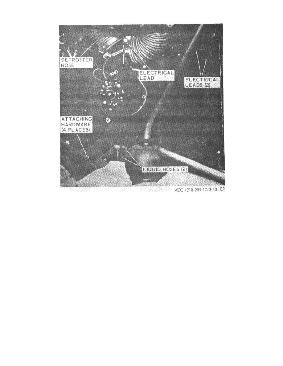 Figure 71.33. Personnel heater and defroster.
move the blower motor to expose the blower attaching
(1) Remove the three screws (50, fig. 71.35)
hardware. Remove the blower.
and the intake cover (48) from the casing.
After removing the three screws (50),
b. Installation. Install in reverse of removal.
remove the circulating air blower
assembly (49) from the casing. Withdraw
197. Space Heater
the wire through the rubber grommet (23)
Repair procedures for the space heater are
in the casing during removal. If the
similar to the procedures described in paragraph 194
control head has not been removed,
with the following exceptions. Refer to figure 71.12 for
disconnect the wire at its terminal in the
electrical schematic.
control head.
a.
Removal. (fig. 71.34). Disconnect electrical
(2) Loosen the setscrew (45) and remove the
leads and the flexible tubing from the space heater
fan (52) from the motor shaft. Insert a
assembly. Remove attaching hardware and the space
screwdriver through the motor clamp
heater.
assembly to loosen clamp screw (46).
b.
Circulating Air Blower Removal and
Disassembly.
AGO 5667A
36
|
|
Privacy Statement - Press Release - Copyright Information. - Contact Us |
