 |
|||
|
|
|||
|
|
|||
| ||||||||||
|
|
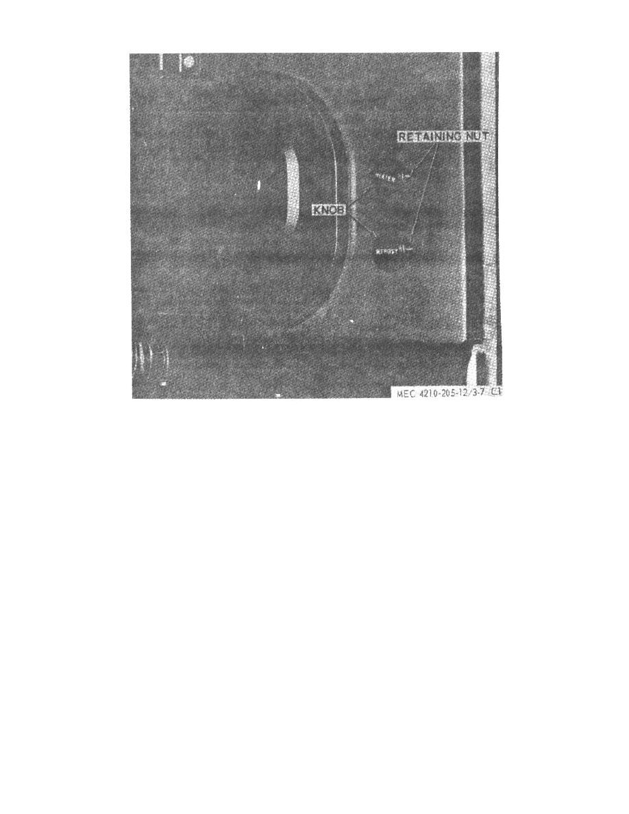
 Figure 71.27. Personnel heater and defroster
switch, removal and installation.
189. Circulating Pump Switch
tube to cool. The switch should return to
(fig. 71.26).
cold position at 200to 300 .
F
a. Removal. Disconnect electrical leads from the
(3) If a correctly adjusted switch does not
switch. Remove retaining nut and switch.
meet these requirements, replace the
flame switch.
b. Installation. Install in reverse of removal.
d.
Flame Switch Installation. To install the flame
switch, position the switch in the control head; secure
190. Personnel Heater Switch
with the mounting nut. Connect the wiring as indicated
(fig. 71.27).
in fig. 71.7.
a. Removal. Disconnect the electrical leads from
the switch.
Remove the knob and retaining nut.
188. Limit Switch
Remove the switch.
(fig. 71.25).
b. Installation. Install in reverse of removal.
a. Removal. Disconnect the wires at the two limit
switch terminals.
Remove attaching screws, limit
switch, and switch retainer.
b. Installation. Install in reverse of removal.
AGO 5667A
25
|
|
Privacy Statement - Press Release - Copyright Information. - Contact Us |