 |
|||
|
|
|||
|
Page Title:
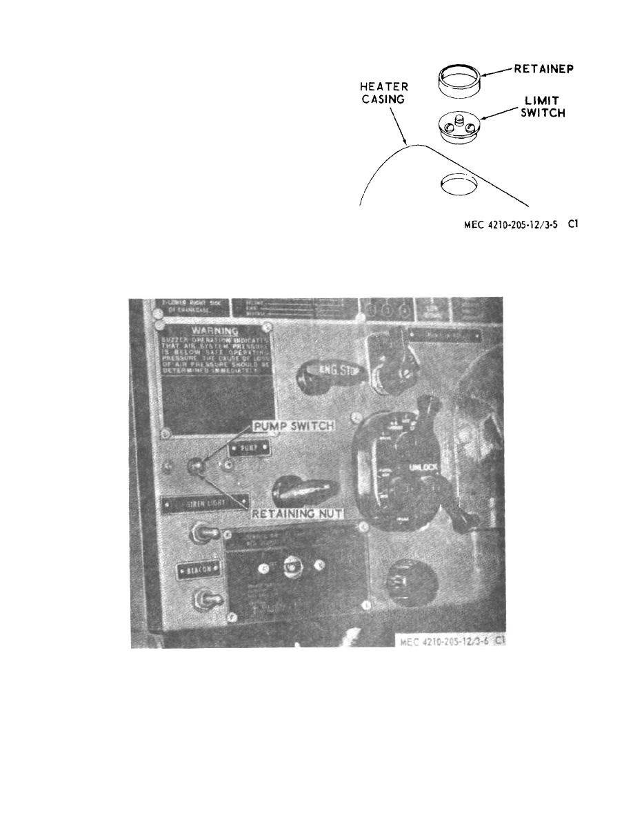
Figure 71.26. Circulating pump switch. |
|
||
| ||||||||||
|
|
 (2) With the flame switch at room
temperature, loosen the adjusting screw
until a distinct click is heard. Then tighten
the screw until a second click occurs. At
this point continue to tighten for three-
eighths of a turn to correctly position the
adjusting screw.
c.
Flame Switch Test.
(1) At room temperature, check for continuity
across terminals 2 and 4 and terminals 2
and 5 (fig. 71.23) with an ohmmeter. If
continuity exists, continue the test.
(2) Apply heat to the flame switch tube. The
switch should change to hot position at
across terminals 1 and 2 and terminals 1
Figure 71.25. Limit switch, removal and installation.
and 5. Allow the
Figure 71.26. Circulating pump switch.
AGO 5667A
24
|
|
Privacy Statement - Press Release - Copyright Information. - Contact Us |
