|
| |
ENGINE DIVISION SERVICE MANUAL
TM 5-4210-230-14&P-1
ENGINE
To obtain proper bearing assembly with the correct
"crunch," care must be taken when tightening the clamping
bolts and nuts to make sure they are drawn down alternately
and evenly using a tension wrench and tightened as specified.
Rod caps or blocks must not be filed, lapped or
reworked in any other manner in order to reduce clearance.
While such practice may make a tighter fit at top and bottom,
it will result in an out-of-round bore and bearing shell
distortion.
Main and connecting rod bearings are designed with
the "spread" (width across the open ends) slightly larger than
the diameter of the crankcase bore or connecting rod bore into
which they are assembled. For example, the width across the
rod bearing not in place is approximately .025" more than
when the bearing is in position. This condition is designed
into the bearing to cause it to spread outward at the parting
line when "crush" load is applied by tightening the nuts and
bolts. Some of this "snap" may be lost in normal use, but the
bearing need not be replaced because of a nominal loss of
this condition.
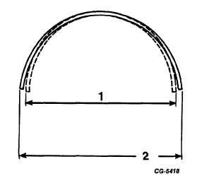
This condition causes the bearing to fit snugly in the
respective bore. The bearing must be "snapped" or lightly
forced into its seat, Figure 125.
Fig. 125 Illustrating Bearing Spread
1.
O.D. of bearing
2.
Spread of bearing
when installed
before installation
is the same as the
diameter of the
crankshaft or conn.
rod bore.
BEARING SPREAD DIMENSIONS
Bearing O.D.
Specified
Spread of
(Installed)
Spread
Bearing "A"
Fig. 122
Connecting Rod Bearings
2.6245-2.6250
.030-.0305
2.6545-2.6555
Main Bearings
No's 1, 2, 4 & 5
3.3160-3.3152
.0200-.0208
3.336
No. 3 (Thrust)
3.3160-3.3152
.0020-.0168
3.318-3.332
B. Fitting Main Bearings
To obtain an accurate reading using the Plastigage
method of checking, all bearing caps must be in place and
torqued to specifications.
1.
Remove one bearing cap and insert. Remaining caps
are left tight while checking the fit of this bearing.
2.
Wipe the oil from all contact surfaces such as
crankshaft journal, bearing insert, bearing caps, etc.
3.
Place a piece of Plastigage the full width of the
bearing surface on the crankshaft journal (or bearing
cap insert) approximately ¼ " off center. Install
bearing cap and tighten cap bolt to recommended
torque.
NOTE: Do not turn crankshaft while making
check with Plastigage.
4.
Remove bearing cap and insert.
5.
Do not disturb Plastigage. Using the Plastigage
envelope, measure the widest point of the Plastigage,
Figure 126. This reading indicates the bearing
clearance in thousandths of an inch.
6.
If the bearing clearance is not within specifications,
the crankshaft must be reground and underside
bearings installed.
CGES-210 Page 50
PRINTED IN UNITED STATES OF AMERICA
|