|
| |
ENGINE DIVISION SERVICE MANUAL
TM 5-4210-230-14&P-1
ENGINE
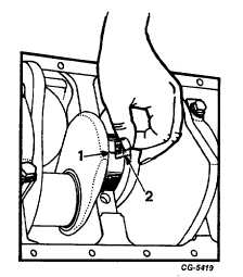
Fig. 126 Checking Main Bearing Clearance
1. Plastigage flattened
2. Gauge
7.
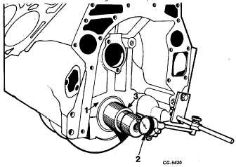
The third crankshaft bearing controls the crankshaft
thrust and provides initial location of the crankshaft
in relation to the crankcase. Use dial indicator to
check end play, Figure 127.
C. Fitting Connecting Rod Bearings
1
Remove bearing cap and wipe oil from face of
bearing insert-and exposed portion of crankshaft
journal.
2.
Place a piece of Plastigage on the bearing surface
the full width of the bearing about ¼ " off center.
Fig. 127 Checking Crankshaft End Play
1.
Crankcase
3.
Crankshaft
2.
Dial indicator
3.
Install cap and tighten to recommended torque.
NOTE: Do not turn crankshaft while Plastigage is in
place.
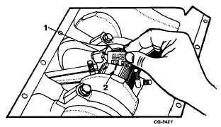
4.
Remove bearing cap and use Plastigage scale to
measure widest point of Plastigage, Figure 128. This
reading
indicates
the
bearing
clearance
in
thousandths of an inch.
Fig. 128 Checking Connecting Rod Bearing Clearance
1. Gauge
2. Plastigage flattened
5.
If the bearing clearance is not within specifications,
the crankshaft must be reground and undersize
bearings installed.
6.
Check the connecting rod end clearance using a
feeler gauge as shown in Figure 129. Excessive
clearance may require replacement of rods or shaft.
The check should be made to make certain the
specified running clearance exists. Lack of clearance
could indicate a damaged rod or a rod bearing out of
position.
CGES-210 Page 51
PRINTED IN UNITED STATES OF AMERICA
|