|
| |
TRUCK SERVICE MANUAL
TM 5-4210-230-14&P-1
BODIES AND CABS
is of fin-tube construction. Refrigerant entering the evaporator
through the expansion valve vaporizes and absorbs heat from
the walls of the evaporator tubes and fins which, in turn, draw
heat from the air forced through the evaporator by the blower.
This absorbing of heat by the refrigerant results in a flow of
cool air from the system. Moisture from the air condensing on
the evaporator is drained to the exterior of the vehicle via a
drain tube.
Air Filter
On vehicles equipped with air conditioning, a
replaceable air filter is located between the blower and the
evaporator to keep the evaporator fins clean to assure
efficient heat transfer.
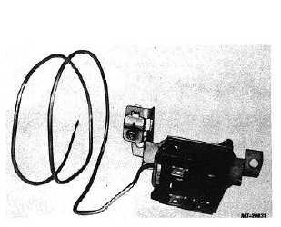
Fig. 12 Thermostatic Temperature Control Switch
Thermostatic Temperature Control Switch
The thermostatic temperature control switch (Fig.
12) is located in the bottom of the combination unit. This
switch performs these functions:
1.
Turns air conditioning system "ON" and "OFF".
2.
Engages and disengages magnetic clutch to start
and stop operation of the refrigerant compressor as
needed to maintain desired cab cooling.
3.
Overrides the engine's radiator shutter control to
open the shutters whenever air conditioning system
is turned on.
4.
Supplies current to the engine fan drive override
switch (where equipped).
The thermostatic switch is controlled through a cable
connected to the top (A/C) lever of the control panel
assembly. With the control lever in the "OFF" position, the
magnetic clutch will not engage (air conditioning system will
not operate).
As the lever moves from the "OFF" position, two sets
of contacts close. The smaller set of contacts, which remain
closed through all remaining lever travel, connect feed
terminal "2" to terminal "3" supplying current to the shutter
override solenoid valve and the fan drive override switch
(where equipped). (See wiring circuit diagram, Fig. 17.) The
larger set of contacts connect feed terminal "2" to terminal "1"
to supply current, via terminals "1" and "2" of the low pressure
switch relay, to engage the magnetic clutch. (See Fig. 17.)
Compressor cycling (engaging and disengaging the magnetic
clutch) is accomplished by making and breaking the larger set
of contacts.
Cycling temperature setting is determined by position
of the air conditioning control (A/C) lever. Moving the lever to
the right decreases the control temperature with maximum
cooling obtained when lever is in "COLD" position.
Making and breaking of the larger set of contacts (to
engage and disengage the magnetic clutch) is controlled by a
bellows connected to a capillary tube filled with refrigerant.
The other end of the capillary tube is located in
evaporator core where it senses evaporator fin temperature.
When the fin temperature in the evaporator is higher
than the control temperature setting, the refrigerant in the
capillary tube expands moving the bellows, overcoming spring
pressure and closes the contacts to engage the clutch
(operate the compressor). When temperature of the air flow
is decreased sufficiently the refrigerant in the capillary tube
contracts allowing spring pressure to open the contacts and
disengage the clutch.
This compressor on-compressor off cycle repeats as
often as necessary to maintain the desired cab temperature.
Low Pressure Switch
A low pressure switch (Fig. 13), located in the
evaporator outlet tube, is used to protect the refrigerant
compressor from damage in the event of refrigerant loss or if
ambient temperature is too low to provide sufficient
evaporation of refrigerant.
CTS-2731 Page 8
PRINTED IN UNITED STATES OF AMERICA
|