|
| |
TRUCK SERVICE MANUAL
TM 5-4210-230-14&P-1
BODIES AND CABS
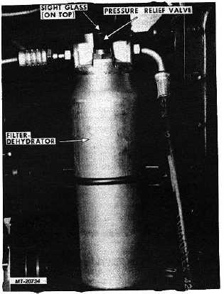
Fig. 9 Filter Dehydrator
Filter-Dehydrator
The filter-dehydrator (Fig. 9) receives the high
pressure liquid refrigerant from the condenser and removes
any foreign material or moisture which may have entered the
system. This unit also serves as a reservoir to store liquid
refrigerant until it is needed by the evaporator.
The filter-dehydrator unit incorporates a pressure
relief valve which discharges refrigerant into the atmosphere if
pressure exceeds 3100 kPa (450 psi). The valve reseals itself
automatically when pressure drops below 2750 kPa (400 psi)
and does not expel the entire refrigerant charge.
A sight glass used to determine need for adding
refrigerant is located at the top of the filter-dehydrator.
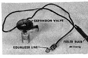
Expansion Valve
The expansion valve (Fig. 10) is located between the
filter-dehydrator and the evaporator and regulates the flow of
refrigerant entering the evaporator.
Leaving the expansion valve, the refrigerant starts to
evaporate and expand entering the evaporator as a low
pressure liquid-gas mixture.
Attached to the top of the expansion valve is a
capillary tube with a feeler bulb which is clamped to the outlet
(suction) pipe of the evaporator. The sealed bulb and tube
are filled with gas which expands and contracts according to
temperature surrounding the bulb. The feeler bulb senses
temperature of refrigerant leaving the evaporator. A second
capillary tube is attached under the valve diaphragm and is
connected to the evaporator outlet (suction) pipe. This is an
equalizer line which senses suction pressure. Together, they
regulate the amount of refrigerant entering the evaporator.
Fig. 10 Expansion Valve
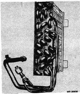
Fig. 11 Evaporator Core
Evaporator
The evaporator core (Fig. 11), mounted in the
combination heater-evaporator-blower unit,
CTS-2731 Page 7
PRINTED IN UNITED STATES OF AMERICA
|