|
| |
TM5-4210-229-14&P
6-11. OIL PUMP, FILTERS, AND COOLER MAINTENANCE (Continued).
d. End clearance check.
(1) Place a strip of plastigage (Appendix D,
Item 40a) onto rotors and cover with hous-
ing, using a new O-ring in groove.
(2) Secure housing to front cover.
(3) Remove housing and measure the plas-
tigage. The limits 0.0020 to 0.0048 in
(0.0508 to 0.1219 mm) must be maintained.
(4) Remove the Plastigage and outer rotor.
Compressed air used for cleaning or drying can
create airborne particles that may enter the
eyes. Pressure shall not exceed 30 psi
(206 kPa). Wearing of goggles is required to
avoid injury to personnel.
CAUTION
Do not use wire brushes or steel scrapers for
removing deposits.
e. Drain and blow out any foreign matter inside of
the cooler. Be certain that all passages are clean
and clear before installation.
f. Air pressure test.
Use adequate safety precautions when per-
forming the following tasks.
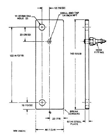
(1) Construct two plates as specified.
(2) Fasten plates, using new oil cooler gaskets,
to the cooler.
(3) Install an air pressure hose to the cooler.
(4) Immerse the assembly in a container of
water, heated to 120° F (49° C). This sta-
bilizes the metal parts of the cooler.
6-25
|