|
| |
TM 5-4210-220-34
3-7.
TRANSMISSION - Continued
NOTE
If special tool J26598-A is not available, install the
snap ring with snap ring pliers. Do not scrape the
ground sleeve splines during installation.
(8) Install rebuilt stator assembly by rotating
clockwise. The stator should lock if
counterclockwise rotation is attempted.
as.
Installation Valve Bodies
NOTE
Pre-set to 10 ft lb (13 Nm), the valve body torque
wrench, J29612, can be utilized to tighten all
valve body bolts.
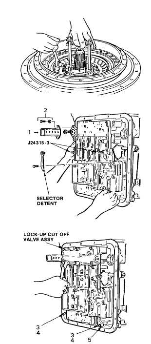
(1)
Install two guide screws J24315-3 into
opposite holes in the transmission
housing.
(2)
Install the control valve assembly using
the guide screws as support, onto the
transmission. The groove in the
selector valve must engage the pin on
the detent lever.
(3)
Install the lubrication check valve baffle
(1) and retain it with two 1/4 20 1 1/2 in.
bolts (2).
(4)
Install two 1/4 20 X 1 1/2 in. bolts (3)
and two 1/4 in. washers (4) through the
oil transfer plate (5) and into the
transmission housing. Bolts retain the
oil transfer plate, separator plate and
control
valve
assembly
to
the
transmission housing. Tighten the
bolts to 12 ft lb (16 Nm).
(5)
Install thirteen 1/4 20 X 3 in. bolts
through the valve body assembly and
into the housing. Remove two guide
screws
J24315
and
install
two
remaining 1/4 20 X 3 in. bolts. Install
the selector detent and retain it with a
1/4 20 X 2 1/2 in. bolt. Tighten the
bolts to 10 ft lb (13 Nm).
(6)
Install the lockup cutoff valve body
assembly. Retain it with eight 1/4 20 X
3 in. bolts. Tighten the bolts to 10 ft
(13 Nm).
3-81
|