|
| |
TM 5-4210-220-34
3-7.
TRANSMISSION - Continued
(2) Install the PTO idler gear (8) and spindle
(9). Install the gear and spindle into the
bore near the top of the converter
housing, alining the bolt hole in the
spindle with the tapped hole in the
housing.
(3) Retain the gear and spindle with the 1/2-
13 X 3 1/4 in. self-locking bolt (10).
Tighten the bolt to 97 ft lb (132 Nm).
(4) Install three bolts (15) through holes in
pump drive gear (14) retain scavenge oil
pump (11). Use one bolt (13) to attach
suction tube (12). Tighten mounting
bolts to 32 ft lb (43 Nm), and suction
mounting bolt to 43 ft lb (58 Nm).
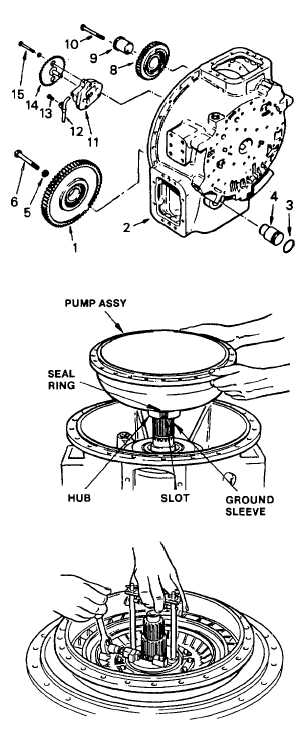
ar.
Installation Torque Converter Pump and
Stator Assembly (1) Install torque converter
pump assembly onto ground sleeve. Check
that seal ring is on the hub.
(2)
Pump bearing is a press fit on the
ground sleeve. It may be necessary to
heat hub and bearing area of the pump
assembly to 300 deg. F (149 deg. C) in
oil bath before installation.
(3)
Aline the slots in the pump hub with
tangs in the charge oil pump drive gear
as the pump is being installed.
(4)
Install spacer onto the converter ground
sleeve.
(5)
Place snap ring into tool J26598-A as
follows. Close the jaws of the tool by
rotating the adjusting nut. Place the
snap ring in the tool, under the safety
guards. Position the jaws of the tool in
the snap ring gap. Open the jaws of
the tool by rotating the adjusting nut to
the stop nut.
(6)
Place the fixture, with snap ring over
the ground sleeve. Open the safety
guards to position the snap ring.
(7)
Close the jaws and set the snap ring in its
bore in the ground sleeve. Remove the tool.
3-80
|