|
| |
TM 5-4210-220-34
3-7.
TRANSMISSION - Continued
p.
Control Valve Body Assembly, Inspection, Repair And Assembly
The valve body assembly contains a number of springs, some of which are similar and can be mistakenly
Interchanged. If the springs are not reinstalled in the same locations from which removed, erratic shift
patterns may occur. For these reasons, it is recommended that each spring, at removal, be tagged with
its item number, and placed in valve body parts tray set J33163. This will simplify correct assembly of the
valve body components.
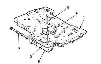
(1)
Place valve assembly on the work table,
modulator valve body (4) upward.
(2)
Remove manual selector valve (7).
(3)
Remove
three
bolts
(6)
that
retain
modulator valve body (4). Remove control
valve body (5) while holding oil transfer
plate (1) and separator plate (3) together.
(4)
Invert the oil transfer and separator
plates (separator plate on top) while holding
them firmly together. Place them on the
work table.
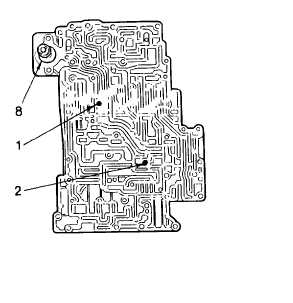
(5) Lift or slide separator plate (3) off oil transfer plate (1). Note check ball locations in the oil transfer plate. Make
a sketch or list that will identify the ball sizes and locations of balls in oil transfer plate. This will assist in
reassembly. Remove the balls.
(6) Check ball # 1 (1/4 in. ball) is located in the
third clutch pressure line, next to the 4-5
relay valve. Its function is to restrict the
feed to third clutch for clutch overlap and
allow full exhaust.
(7) Check ball # 2 (1/4 in. ball) is located in the
second clutch pressure line next to the 3-4
relay valve. Its function is to restrict the
feed to second clutch for clutch overlap and
allows full exhaust.
(8) Remove the lubrication pressure regulator
valve (8) from the oil transfer plate.
Depress cup washers and remove pin.
Release washer and remove it. Remove
spring and valve. Remove valve pin from
the’ oil transfer plate.
(9) Disassemble the modulator valve. Before removing pin (9) note position of adjusting ring (10). Reinstall in
same position as removed. Press adjusting ring (10) inward and remove retainer pin (9). Release the
adjusting ring and remove spring (11), modulator valve (12) and modulator actuator valve (13).
3-25
|