|
| |
TM 5-4210-220-34
3-7.
TRANSMISSION - Continued
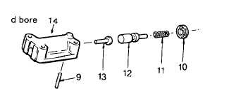
(10) Inspect valve body (14) and valve (12) for
damaged bore or scored valve surface.
Replace necessary parts.
(11) Install
modulator
actuator
valve
(13),
modulator valve (12), spring (11) and
adjusting ring (10), into bore of valve body
(14).
(12) Compress the spring, and install retainer pin (9) into valve body (14) to retain adjusting ring (10). Be sure the
adjusting ring is in the same position as it was before removal.
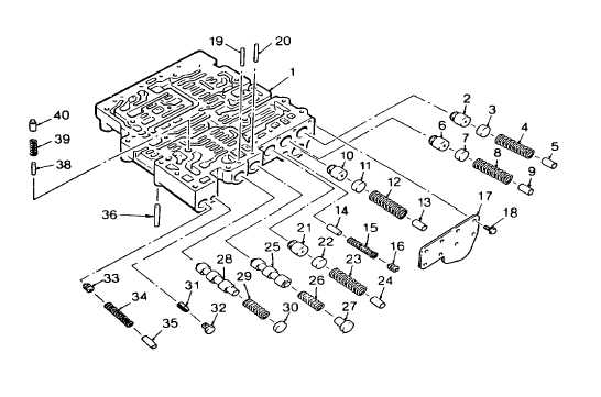
(13) Remove priority valve (40), spring (39), and valve stop (38) from the control valve body (1).
(14) Position valve body (1), flat side upward, on the work table. Remove plug (32) and screen assembly (31).
(15) Remove eight bolts (18) while holding trimmer cover (17) against spring pressure. Relieve pressure and
remove cover (17).
(16) Remove spring (4), valve stop (5), trimmer plug (3), and trimmer valve (2).
(17) Remove spring (8), stop (9) plug (7), and valve (6).
(18) Remove spring (12), stop (13), plug (11), and valve (10)
(19) Remove valve (16), spring (15), and stop (14).
(20) Remove spring (23), stop (24), plug (22), and valve (21).
3-26
|