|
| |
TM 5-4210-220-12
4-32. FRONT AXLE-Continued
(3)
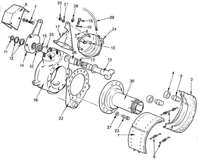
Install air chamber bracket (17) to ball socket (16) using bolts (18) and washers (19). Tighten bolts to 85
ft lb (115 Nm).
(4)
Apply pipe sealant (item 22, Appendix E) to fitting threads and install brake chamber hoses (29) to brake
chamber (24). Tighten fittings firmly.
(5)
Apply a light coat of grease (item 16, Appendix E) to journals and spines on camshaft (13), and slide it
through bore in ball socket. Be careful not to damage seals inside bore. Remove excess grease from
area around camshaft bore and make sure that the camshaft head is clean and grease free.
(6)
Connect brake shoes (1 and 2) together using retaining springs (6). Place brake shoes around axle
spindle so that lower ends ride on anchor pin (A).
(7)
Install return spring (3).
(8)
Lever each brake shoe in turn and install cam rollers and pins (4 and 5) between brake shoes and
camshaft head.
4-609
|