|
| |
TM 5-4210-220-12
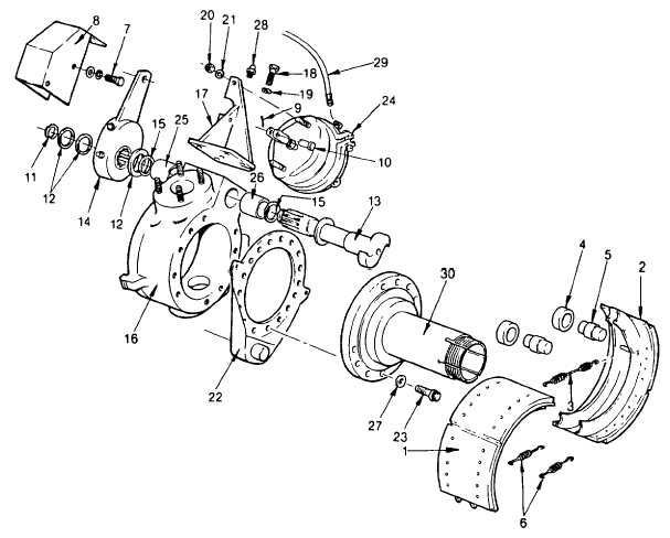
4-32. FRONT AXLE
4-32.5 Brake Assembly-Continued
(9)
Install shim washer (15) and slack adjuster (14). Be sure adjustment screw on side of slack adjuster is
facing away from air chamber.
(10)
Install appropriate shim washers (12) (refer to INSPECTION step 7, if necessary, to determine shim
requirement). Install lock ring (11).
(11)
Attach slack adjuster to brake chamber clevis using clevis pin (10) and cotter pin (9). If advanced too
far, depress locking sleeve on side of slack adjuster and turn slack adjuster toward brake chamber clevis
to line up clevis pin holes.
(12)
Lubricate camshaft via grease nipple (28) with grease (item 16, Appendix E). Do not over lubricate as
this will damage the seals.
(13)
Install wheel hub and brake drum as detailed in para. 4-32.3. Adjust brake as outlined in ADJUSTMENT
procedure preceding.
(14)
Be sure axle is refilled with oil, see lube order LO 5-4210-220-12, when installation and adjustment of the
brake is complete.
4-610
|