|
| |
TM 5-4210-220-12
4-15. AUXILIARY POWER UNIT - Continued
4-15.8 Engine Intake and Exhaust Valves - Continued
(9)
Inspect valve guides. If guides are excessively
worn (see table), are grooved or have carbon
deposits, replace valve guide. (See REPAIR
following).
(10)
Inspect valve seats if badly scored or they have
an irregular wear pattern resurface seat. If seat
diameter is greater than 1.06 in. (27 mm)
(intake) 0.91 in. (23 mm) (exhaust) replace seat.
See REPAIR following.
(11)
Lap valves and seats with valve grinding
compound (item 31, Appendix E) even if neither
is replaced.
(12)
Inspect valve springs. Replace if broken,
cracked or chipped. Check free length equals
1.65 in. (42 mm).. With load of 51 lb (23 kg)
spring length must be 1.26 in. (32 mm).
Replace
if
spring
will
not
meet
these
specifications.
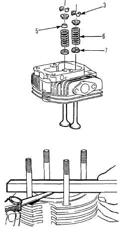
INSTALLATION
(1)
Install valves in cylinder head.
(2)
Install valve spring retainers (7) valve springs
(6) valve seal (5, intake only), upper retainer
over valve shafts.
(3)
Compress each spring in turn and install spring
retainer (3) over valve shaft.
(4)
Install injector into cylinder head, see para. 4-
15.7 INSTALLATION.
(5)
Replace push rod cover upper and lower seals
on cover. Install cover in engine block.
(6)
Rotate flywheel until piston is at top dead
center. Measure piston crown face to cylinder
edge clearance.
(7)
Crown face of piston must be between 0.008 in.
(0.20 mm) higher and 0.006 in. (0.15 mm) lower
than cylinder edge.
(8)
Adjust clearance by selecting one of the
following cylinder head gaskets.
4-164
|