|
| |
TM 5-4210-220-12
4-15. AUXILIARY POWER UNIT - Continued
SIZE
PART NO.
0.020 in. (0.50 mm)
520.4730.030
0.024 in. (0.60 mm)
520.4730.031
0.028 in. (0.70 mm)
520.4730.032
0.032 in. (0.80 mm)
520.4730.033
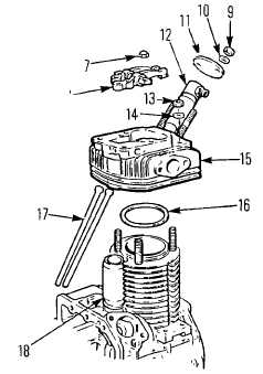
(9)
Install new head gasket (16) onto cylinder block.
(10)
Install push rods (11) in. cover, ensuring the tips seat
in the tappets.
(11)
Install cylinder head (15) over studs, ensuring push
rod cover seal fits into head recess.
(12)
Install rocker arm assembly (8) over studs. Exhaust
rocker has two adjusting screws and mounts on the
exhaust side of the engine.
(13)
Guide the push rods into correct rocker arm. Push
rod next to cylinder is inlet push rod. (Push rods will
be crossed over in tube if correctly installed).
(14)
When rocker arm and push rods are engaged, install both acorn nuts (7) and jam nuts (13) onto cylinder head
studs.
(15)
Tighten to 29 ft lb (39 Nm), working crosswise.
(16)
Adjust valve tappet clearance to 0.006 in. (0.15 mm) with piston at top dead center of compression stroke.
(Flywheel mark 3 alined with shroud mark 2).
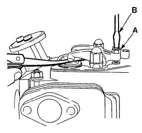
(17)
When adjusted, tighten rocker arm locking nuts (A)
ensuring adjuster screw (B) does not rotate.
(18)
With piston at top dead center of compression stroke,
operate decompression lever. Check exhaust valve
lowering starts when lever has traveled halfway
between "ON" and "OFF" positions.
(19)
Adjust by altering set screw at rear of exhaust rocker
arm. Adjust until clearance between decompression
spindle and bottom of screw is 0.036 - 0.044 in. (0.9 -
1.1 mm) with lever in the "OFF" position.
(20)
Set compression release and rotate flywheel. Ensure
decompression lever resets within 1 full rotation of the
engine
(21)
Install valve cover (4) with new gasket (5) on cylinder
head
4-165
|