|
| |
TM 5-4210-220-12
4-12. CAB - Continued
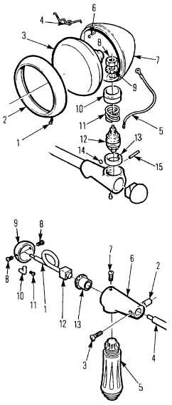
4-12.3 Spotlight - Continued
(4) Remove headpost (12) from lamp housing and remove nylon ring (13) from headpost.
(5) Inspect parts for wear and corrosion. Replace defective parts.
(6) Install nylon ring (13) on headpost (12) Lubricate headpost gear and nylon ring with white grease (Item 34,
Appendix E) and insert headpost in lamp housing.
NOTE
Hardened steel washers form protective barriers between spring (11), bushing (10) and headpost
(12) Be sure these washers remain in place when assembling lamp head.
(7)
Install spring (11) and bushing (10) Secure
bushing with pin (15).
(8)
Install screw (14) Tighten it firmly to
prevent nylon ring (13) from rotating inside
the lamp housing.
(9)
Install lamp shell (7) to headpost using
washer (9) and nut (8).
(10)
Assemble lamp ring (2) and bulb (3) using
springs (4) Attach wires (5 and 6) to bulb,
and wire (5) to headpost.
(11)
Install lamp ring to lamp shell and secure
with screw (1).
b.
Handle Housing, Handle, and Lamp Switch
Repair.
NOTE
To replace handle and handle housing
assembly, carry out steps 1, 2 and 11
To replace switch and wire assembly
carry out steps 1, 4, 5, 7, 8, 9, and 11.
(1)
Cut wire butt splice out of wire (1) and
discard. Be sure to cut as close to splice as
possible.
(2)
Remove screw (3) and wedge (2) Pull
handle and housing assembly off shaft (4).
(3)
Pull handle (5) from housing (6).
(4)
Remove screw (7), screws (8), switch cap
(9) and switch assembly (12).
(5)
Remove screw (11) and toggle (10).
4-92
|