|
| |
TM 9-254
4-1.
Torque Wrench - Continued
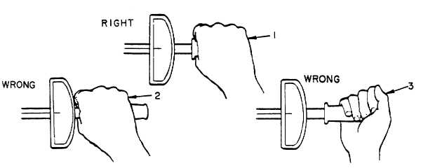
Figure 4-3. Torque Wrench - Hand Position
NOTE
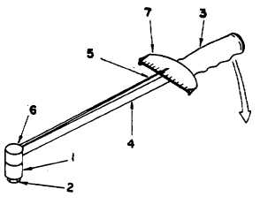
In steps (3) through (7) refer to figure 4-4.
(3)
Place correct size socket (1) on bolt head or nut (2), begin by turning wrench handle (3) clockwise for a
right-hand bolt (standard).
(4)
When bolt head (2) or nut begins to feel tight, turning force on handle (3) will start to flex or bend beam
(4). Pointer (5) is supported only at drive end (6) of wrench and therefore will not bend with beam.
(5)
Scale (7) is fastened to beam (4) near handle (3). As beam bends, scale (7) will move with beam (4)
under pointer (5) so that pointer indicates numbers away from 0.
(6)
Watching pointer (5), slowly and smoothly continue tightening bolt head (2) or nut until pointer (5)
indicates the correct amount of torque on scale (7).
(7)
When pointer (5) indicates the correct torque on scale (7) slowly release pressure on handle (3).
Figure 4-4. Torque Wrench - Illustrated Use
4-3
|