|
| |
TM 9-254
8-8.
Direct Current (DC) Power Supply - Continued
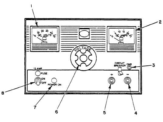
KEY to figure 8-17:
1.
DC VOLTS meter
2.
DC AMPS meter
3.
GND (Ground) terminal
4.
- (negative) output terminal
5.
+ (positive) output terminal
6.
VOLTAGE adjust knob
7.
POWER ON lamp
8.
ON-OFF switch
Figure 8-17. DC Power Supply
(3)
Ground terminal (3) is for a ground lead connection between the power supply and the equipment being
supplied voltage.
(4)
- output terminal (4) is for a lead connection between the power supply and negative terminal of the
equipment being supplied voltage.
(5)
+ output terminal (5) is for a lead connection between the power supply and positive terminal of the
equipment being supplied voltage.
(6)
VOLTAGE adjust knob (6) will increase the current and voltage output at terminals (4 and 5) when
rotated clockwise.
(7)
POWER ON lamp (7) lights when primary power is applied to the power supply.
(8)
ON-OFF switch (8) supplies primary power to the power supply when placed in the ON position.
8-24
|