|
| |
TM 9-254
7-3.
Alternating Current - Continued
d.
Impedance. The impedance of an AC circuit is made up of two components. The first component is the pure
resistance which is the same as that found in DC circuits. The second component is the reactance which is the opposition
to the flow of AC by the inductive and/or capacitive components of a circuit.
(1)
Capacitive Reactance. The reactance of a capacitor is calculated by the formula:
Xc =
1
2 p fc
Where:
Xc is the capacitive reactance in ohms.
f is the frequency in hertz.
c is the capacitance in farads.
p is the constant 3.14159.
(2)
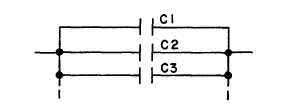
Capacitance. The total capacitance for a circuit can be calculated using the formula in figure 7-6.
For capacitors in parallel:
CT
= C1 + C2 + C3
For more than two capacitors in series
CT
=
1
C1 + C2 + C3
For two capacitors in series:
CT
=
C1 + C2
C1 + C2
Figure 7-6. Capacitance Formulas
7-6
|


