|
| |
TM 9-254
4-17.
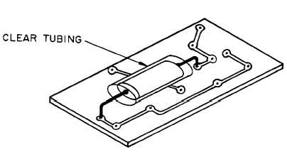
Printed Circuit Boards-Continued
Figure 4-37. Crossing Conductive Lines
(2)
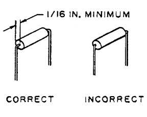
Pigtails should have a minimum clearance of one-sixteenth of an inch between bend and component body as
shown in figure 4-38. When making the minimum bend, support end seal of component with wire-bending
pliers.
Figure 4-38. Minimum Pigtail Bend
(3)
Extremely sharp 90 degree pigtail bends will not be accepted. All bends should be made with a gradual
curve.
(4)
The radius of the bend should be equal to, or greater than twice the lead diameter.
(5)
Component pigtails will extend through the printed circuit boards a minimum of one-sixteenth of an inch
to a maximum of one-eighth of an inch and will be clinched flush with the circuit. The bend or clinch
must be in the same direction as the conductive line to which the pigtail is attached as shown in figure 4-
39. The clinching tool shall be of wood or plastic to prevent damage to the printed circuit or
components.
4-42
|