|
| |
TM 9-254
4-16.
Tinning Wire - Continued
(6)
Remove the wire from the soldering iron and allow it to cool before removing heat shunt from the wire.
Clean tinned wire with alcohol and a medium stiff bristle brush to remove all flux residue.
(7)
Clean the inside of the clamping jaws of the heat shunt (fig. 4-33) with alcohol and a medium stiff bristle
brush to remove all flux residue.
(8)
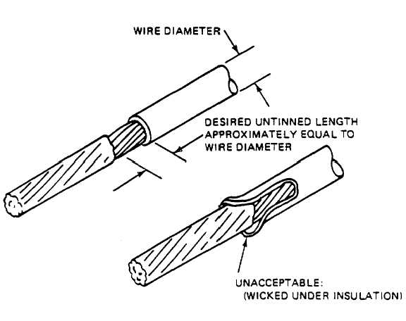
Inspect tinned wire for a smooth even layer of solder (fig. 4-35). The solder coverage on the wire must
be thin enough to show wire strands. Solder coating must not extend under insulation. Wicking
(sucking of solder up along the strands during the tinning process) often makes the solder flow farther
than intended and results in solder under the insulation. Wicking must be avoided.
Figure 4-35. Tinned Wires - Examples
4-17.
Printed Circuit Boards.
a.
Printed Circuit Board Holders (fig. 4-36). To prevent damage during assembly and inspection, the circuit
board should be held by a jig or fixture. This will prevent it from bending, warping, or deforming in any manner. The jig or
fixture will permit the circuit board to be held at each end and fixed at any desired position by use of the wing-nut set
screws in the shaft bearings.
4-40
|

