|
| |
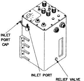
f. Control Unit, Image (fig. 3-56).
Figure 3-56 Image Control Unit
(1) Loosen, but do not remove setscrews in the con-
trast knob, reticle knob, sensitivity knob, symbols knob,
unit test pattern knob, and two boresight knobs from the
front panel.
(2) Remove all knobs from the unit.
(3) Perform purging and charging procedure para
2-5.a.
(4) Purge instrument at 10 psig for 3 minutes.
(5) Ensure relief valve closes at 5 psig.
(6) Leak test all sealed joints, screws, control shafts,
purging valve, and relief valve for minimum of 15 minutes.
(7) Install knobs on front panel.
TM 750-116
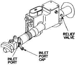
g. Gunner’s Auxiliary Sight, PN 12278900 (fig.
3-57).
Figure 3-57 Gunner’s Auxiliary Sight PN 12278900
(1) Perform purging and charging procedure para
2-5.a.
(2) Purge instrument at 8 psig for 10 minutes.
(3) Ensure relief valve closes at 5 psig.
(4) Leak test for a minimum of 5 minutes.
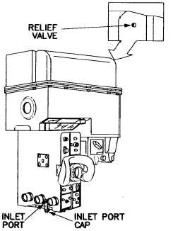
h.
Gunner’s Primary Sight, PN 12282140,
PN 12549761-2, PN 12549761-3, and
PN 9377279-2 (fig. 3-58).
Figure 3-58 Gunner’s Primary Sight PN 12282140,
PN 12549761-2, PN 12549761-3, PN 9377279-2
(1) Perform purging and charging procedure para
2-5.a.
(2) Purge instrument at 6 psig for 5 minutes.
(3) Ensure relief valve closes at 5 psig.
(4) Leak test for minimum of 5 minutes.
3-25
|


