|
| |
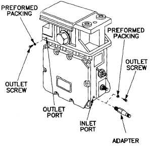
(2) Electronic Cavity (fig. 3-41).
NOTE
See appendix C for Service Kit containing re-
placement parts for M1 and M1Al Tanks.
Figure 3-41 Laser Rangefinder Electronics Cavity
(a) Remove inlet screw with preformed packing
attached.
(b) Remove outlet screw with preformed packing
attached.
(c) Perform purging procedure para 2-5.d.
(d) Purge instrument at 5 psig for 5 minutes.
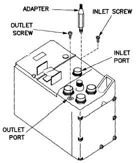
b. AN/VVG-2 Laser (fig. 3-42).
Figure 3-42 AN/VVG-2 Receiver - Transmitter
(1)
(a)
(b)
minutes.
(2)
TM 750-116
Electronics Compartment.
Perform purging procedure para 2-5.d.
Purge electronics compartment at 8 psig for 5
Receiver-Transmitter (R/T) Compartment.
Refer to para 4-12.b.(1) for procedures.
NOTE
Ensure nitrogen is escaping from the relief valve.
If not, repair as necessary.
(3) Optics Compartment. Refer to para
3-12.b.(1) for procedures.
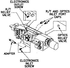
(4) Laser Electronics Unit (fig. 3-43).
Figure 3-43 AN/VVG-2 Electronics Unit
(a) Perform purging procedure para 2-5.d.
(b) Purge instrument at 8 psig for 5 minutes.
3-19
|