 |
|||
|
|
|||
|
Page Title:
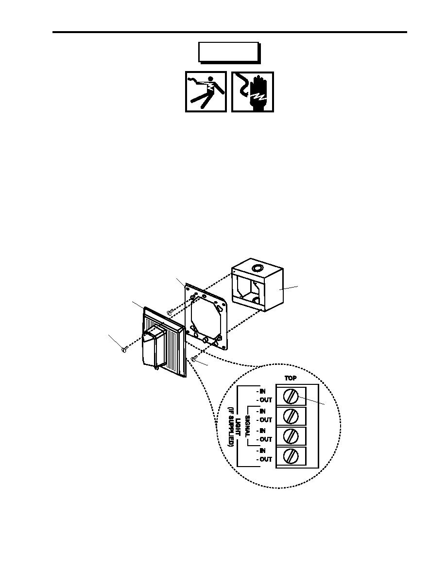
Figure 3. Horn/Strobe Replacement |
|
||
| ||||||||||
|
|
 TM 55-1925-292-14&P
0032 00
WARNING
Replace or repair components only after the affected circuit has been secured,
locked out and tagged out (FM 55-502). Performing replacement with the circuit
energized may result in injury.
2. Using a multimeter, check for voltage at the terminal board (figure 3, item 4). If voltage is present, ensure that
the proper circuit breakers are set to OFF, locked out, and tagged out (FM 55-502). If no voltage is present,
continue with this procedure.
3. Label and disconnect the wiring from the terminal board (figure 3, item 4).
4. Remove the two screws (figure 3, item 5) that secure the mounting plate (figure 3, item 3) to the junction box
(figure 3, item 6), and remove the mounting plate.
3
6
2
1
5
4
Figure 3. Horn/Strobe Replacement
0032 00-5
|
|
Privacy Statement - Press Release - Copyright Information. - Contact Us |
