 |
|||
|
|
|||
|
Page Title:
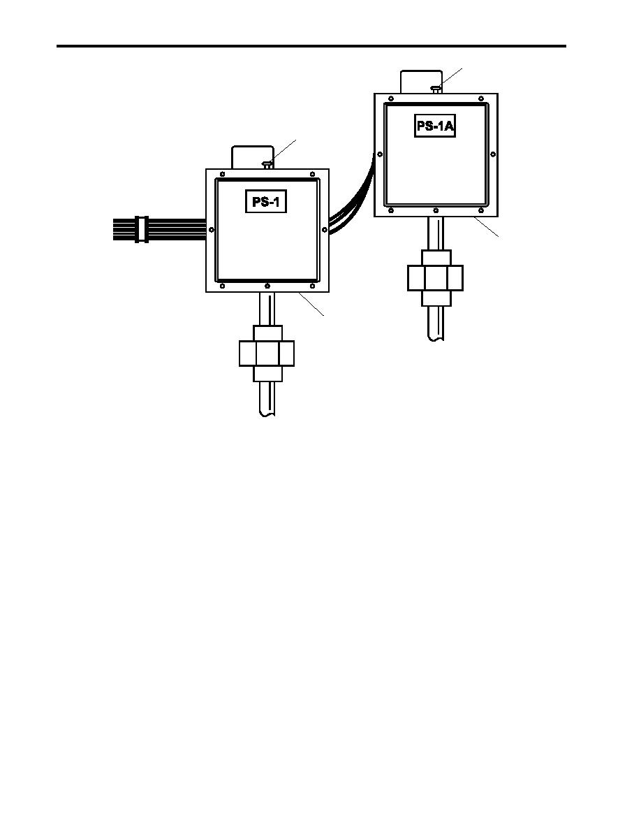
Figure 1. Testing of FM-200 Pressure Switches PS-1 and PS-1A |
|
||
| ||||||||||
|
|
 TM 55-1925-292-14&P
0030 00
4
OPERATED
SET
2
OPERATED
SET
3
1
Figure 1. Testing of FM-200 Pressure Switches PS-1 and PS-1A
8. Verify that the amber strobe lights located in AMS 1, AMS 2, and the engine room have stopped flashing.
9. Verify that the alarm bell located on the exterior main deck has stopped ringing.
10. Manually operate pressure switch PS-1A (figure 1, item 3) by pulling up on the plunger (figure 1, item 4) to the
OPERATED position.
11. Verify that the electric horns located in the engine room and in AMS 1 are sounding.
12. Return pressure switch PS-1A (figure 1, item 3) to the SET position by pressing down on the plunger (figure 1,
item 4).
13. Verify that the electric horns located in the engine room and in AMS 1 have stopped sounding.
14. Check all FM-200 firefighting system components for any signs of corrosion and/or deterioration.
15. Make the appropriate log entries in DA Form 4640 (Harbor Boat Deck Department Log for Class A&B Ves-
sels) and DA Form 4993 (Harbor Boat Engine Department Log for Class A and C-1 Vessels) concerning the
FM-200 System Test.
16. Return the equipment to the desired readiness condition.
END OF WORK PACKAGE
0030 00-2
|
|
Privacy Statement - Press Release - Copyright Information. - Contact Us |