 |
|||
|
|
|||
|
Page Title:
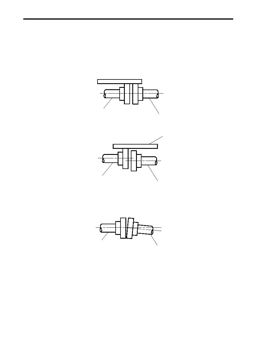
Figure 4. AFFF Pump and Motor Coupling Alignment Detail |
|
||
| ||||||||||
|
|
 TM 55-1925-292-14&P
0029 00
NOTE
Correct alignment of the pump coupling and motor coupling is shown in detail A of figure 3.
Parallel misalignment and angular misalignment are depicted for reference only in details
B and C, respectively.
4. Align the pump coupling (figure 3, item 2) to the motor coupling (figure 3, item 4) ensuring proper parallel and
angular alignment as shown in figure 4.
Pump
DETAIL A
Motor
CORRECT ALIGNMENT
Straight Edge
Pump
Motor
DETAIL B
PARALLEL MISALIGNMENT
Pump
Motor
DETAIL C
ANGULAR MISALIGNMENT
Figure 4. AFFF Pump and Motor Coupling Alignment Detail
5. Once the pump coupling (figure 3, item 2) and the motor coupling (figure 3, item 4) are correctly aligned per
detail A of figure 4, tighten the pump coupling setscrew (figure 3, item 1), and tighten the pump mounting bolts
(figure 1, item 13).
6. Check the alignment of the coupling again. If the alignment is not correct, repeat steps 4-6.
0029 00-4
|
|
Privacy Statement - Press Release - Copyright Information. - Contact Us |