 |
|||
|
|
|||
|
Page Title:
THERMAL HEAT DETECTOR REPLACEMENT |
|
||
| ||||||||||
|
|
 TM 55-1925-292-14&P
0019 00
INSTALLATION
1. Attach the new ionization smoke detector back plate (figure 1, item 6) to the junction box (figure 1, item 7)
with the two screws (figure 1, item 5).
2. Connect the electrical wiring (figure 1, item 3) to the terminals (figure 1, item 2) using the labels from step 3
of Removal as a guide. If an end of line device (capacitor) (figure 1, item 4) was removed during Removal,
connect the capacitor to the terminals. Remove the labels.
3. Install the ionization smoke detector cover (figure 1, item 1).
4. Perform the Follow-On Service procedure at the end of this work package.
THERMAL HEAT DETECTOR REPLACEMENT
REMOVAL
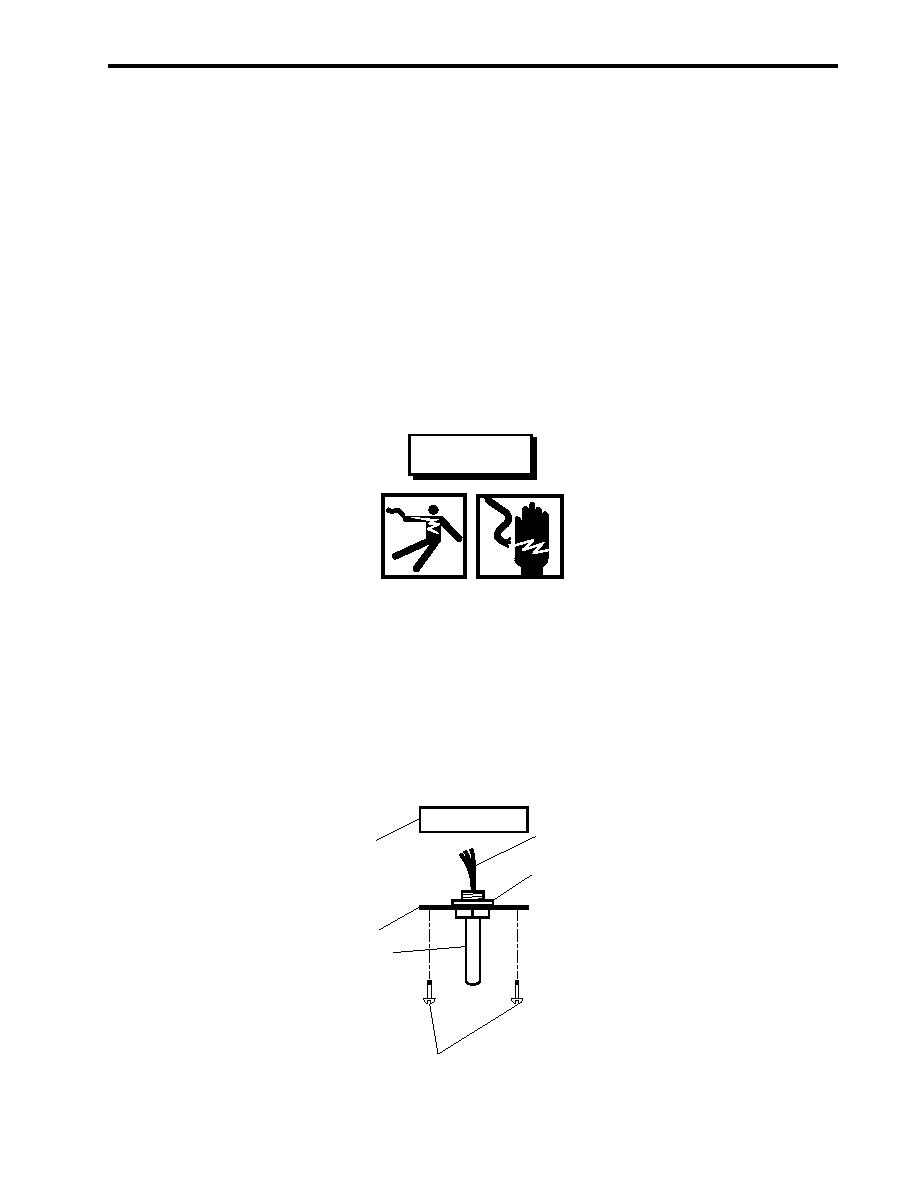
1. Remove the two screws (figure 2, item 1) that secure the junction box cover (figure 2, item 2) to the junction
box (figure 2, item 3), and remove the junction box cover.
WARNING
Take great care when working around electrical equipment. Contact between
unprotected body parts and electrical conductors can cause serious injury or
death. Do not wear jewelry or other conductive items while servicing energized
electrical equipment. Failure to comply with these precautions can cause seri-
ous injury or death.
2. Label and disconnect the wiring (figure 2, item 4).
3. Remove the retaining nut (figure 2, item 5), and remove the thermal heat detector (figure 2, item 6) from the
junction box cover (figure 2, item 2).
4
3
5
2
6
1
Figure 2. Thermal Heat Detector
0019 00-3
|
|
Privacy Statement - Press Release - Copyright Information. - Contact Us |