 |
|||
|
|
|||
|
Page Title:
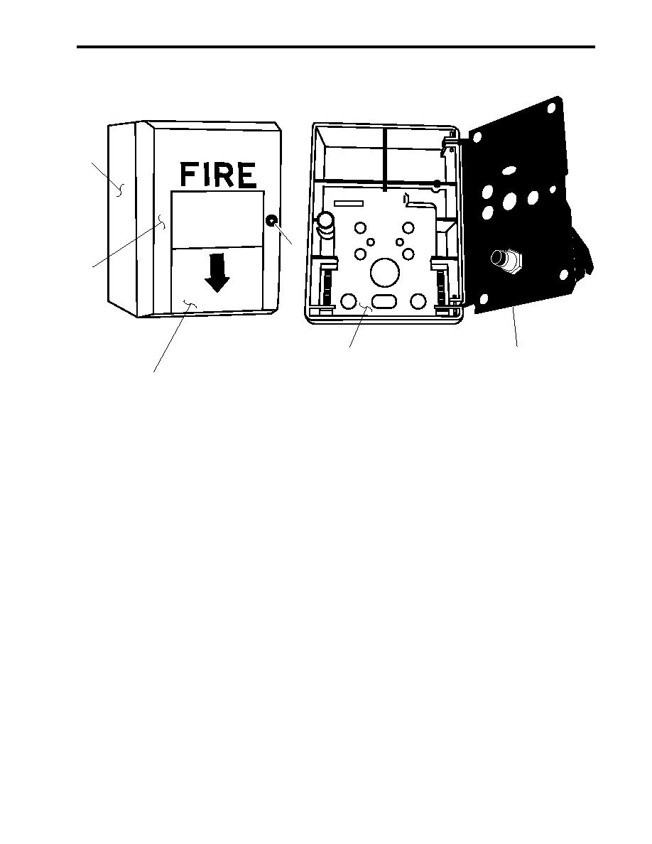
Figure 6. Fire Detection Panel Fire Alarm Pull Station |
|
||
| ||||||||||
|
|
 TM 55-1925-292-14&P
0017 00
1
3
DOWN
PULL
4
5
6
2
Figure 6. Fire Detection Panel Fire Alarm Pull Station
3. Reset the fire detection panel fire alarm pull station (figure 6, item 1) by loosening the locking screw
(figure 6, item 3), opening the hinged cover (figure 6, item 4), locking the body (figure 6, item 5) into the back
plate (figure 6, item 6), and securing the hinged cover with the locking screw.
4. Reset the fire detection panel (figure 2, item 3) by momentarily pressing the RESET LAMP TEST switch
(figure 4, item 4) on the CP-35 CONTROL UNIT (figure 4, item 2) and observe the following:
a. The audible alarm bell (figure 2, item 1) in the EOS sounds and all zone LEDs (figure 2, item 2) illuminate
on the fire detection panel (figure 2, item 3).
b. The audible alarm bell (figure 3, item 1) in the pilothouse sounds and all zone indicators (figure 3, item 2)
illuminate on the remote indicating panel (figure 3, item 3).
c.
The TROUBLE LED (figure 4, item 5) on the CP-35 CONTROL UNIT (figure 4, item 2) illuminates.
d. All audible alarms (figures 2 and 3, item 1) silence and all LEDs (figures 2 and 3, item 2 and figure 4,
items 3 and 5) extinguish.
e. The POWER FLASHING WHEN ON BATTERY LED (figure 4, item 6) is illuminated and not flashing.
f.
All zone LEDs (figure 2, item 2) on the fire detection panel (figure 2, item 3) are illuminated with the green
LED.
5. Perform the Follow-On Service procedure at the end of this work package.
0017 00-7
|
|
Privacy Statement - Press Release - Copyright Information. - Contact Us |