 |
|||
|
|
|||
|
|
|||
| ||||||||||
|
|
 TM 55-1925-292-14&P
OPERATOR AND UNIT MAINTENANCE
FIREFIGHTING, FIRE ALARM, AND FIRE SUPPRESSION SYSTEMS FOR
INLAND AND COASTAL LARGE TUG (LT)
TROUBLESHOOTING INDEX
USE OF THE INDEX
Troubleshooting begins by identifying the equipment and the malfunction. Table 1 contains the operator trouble-
shooting procedures, and table 2 contains the unit troubleshooting procedures. The equipment list is contained
in the left column of the tables, and the malfunctions are listed in the center column of the tables. Once the
correct equipment and malfunction are located, look immediately to the right for the work package and procedure
that correspond to the malfunction. After locating the appropriate work package and procedure, turn to that
procedure, and follow the instructions in the paragraph that follows.
USE OF TROUBLESHOOTING PROCEDURES
Functional flow logic tree troubleshooting procedures are used for all troubleshooting procedures in this manual.
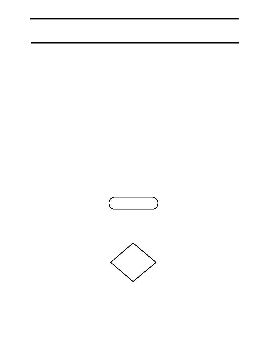
In this troubleshooting style, a pill shaped symbol (figure 1) is used to depict the beginning or end point of a
procedure. Decision points are depicted by diamond shaped symbols (figure 2). Action points, as well as warn-
ings, cautions, and notes are contained in rectangular symbols (figure 3). Procedures that are too large for one
page are joined together by the circular shaped connector symbols (figure 4). The connector symbol will denote
which page and step to go to (or come from) on another page. Finally, when flowchart lines cross, the technician
must ensure that the correct path is followed. Crossing lines (figure 5) indicate that the points connect. Lines that
cross with a jump symbol in the center (figure 6) indicate that the points do not connect. The technician must
correctly follow the arrows to complete the troubleshooting procedure.
Look for the pill shaped beginning symbol in the upper left corner of the procedure. This symbol should contain
the identified malfunction or symptom. Starting from this point, follow the arrowed lines through the procedure.
Remember that the diamond shaped symbols denote a decision step. At each of these points you will be required
to make a decision and to follow the appropriate line for that decision. Continue to follow the arrowed lines
through the procedure until the malfunction or symptom is corrected.
Figure 1. Pill Shaped Symbol
Figure 2. Diamond Shaped Symbol
0007 00-1
|
|
Privacy Statement - Press Release - Copyright Information. - Contact Us |
