 |
|||
|
|
|||
|
|
|||
| ||||||||||
|
|
 TM 55-1925-292-14&P
0005 00
e. Install the detector tube (figure 12, item 5) into the rubber hose (figure 12, item 2) with the arrow on the
detector tube pointing toward the sampling pump (figure 12, item 7).
f.
Insert the detector tube (figure 12, item 5) into the HF sampling port (figure 2, item 3). Ensure that all of
the rubber hose (figure 12, item 2) is inserted into the HF sampling port.
NOTE
Determine the number of strokes required for a proper sample by checking the detector
tube instructions that are in the box of detector tubes or the detector tube itself. The
tube will be labeled as n=number of strokes.
g. With all four fingers on the handle (figure 12, item 8), fully press the knob (figure 12, item 9) with the palm
of the hand until the stroke counter (figure 12, item 1) changes number.
h. Release the knob (figure 12, item 9).
i.
Verify that the end of stroke indicator (figure 12, item 10) has turned a high visibility yellow. Once the
pump has consumed 100 cc of the sample, the end of stroke indicator will return to its black color.
j.
Repeat steps f-i until the proper number of strokes has been performed.
k.
Remove the detector tube (figure 12, item 5) from the HF sampling port (figure 2, item 3).
l.
Install the cap (figure 2, item 2) on the HF sampling port (figure 2, item 3).
m. Observe the color of the detector tube and read the scale printed on the detector tube. Record the
reading.
n. Remove the detector tube (figure 12, item 5) from the hose (figure 12, item 2).
o. Wait two minutes and repeat steps a-m above using a new detector tube.
p. When three consecutive readings of 3 parts per million (ppm) are obtained, the engine room is safe for
reentry.
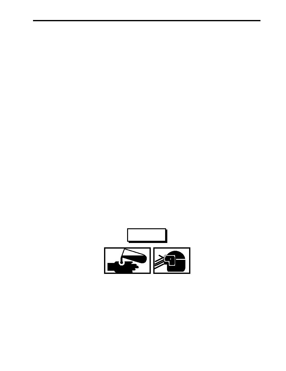
WARNING
Residue from FM-200 fire suppression is a minor irritant to the skin, the eyes, and
the respiratory tract. All personnel who may come in contact with this residue
must wear Personal Protective Equipment (PPE), which prevents the FM-200 resi-
due from contacting the skin, eyes, and/or respiratory tract.
3. After ensuring that no reflash risks exist, the engine room must be ventilated in accordance with TM 55-1925-
273-SDC and the following procedure:
a. If explosive or flammable gases are present, desmoke using the water-driven blower. Desmoke using
the water-driven blower until no flammable gases are detected.
b. If no explosive or flammable gases are present, desmoke using the ventilation exhaust fans in high
speed.
0005 00-13
|
|
Privacy Statement - Press Release - Copyright Information. - Contact Us |