 |
|||
|
|
|||
|
Page Title:
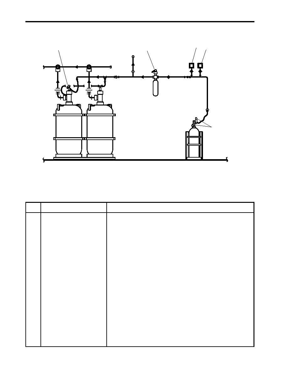
Figure 8. FM-200 Local Actuation Components |
|
||
| ||||||||||
|
|
 TM 55-1925-292-14&P
0004 00
FM-200 LOCAL ACTUATION COMPONENTS
3
4
1
2
5
Figure 8. FM-200 Local Actuation Components
Table 8. FM-200 Local Actuation Components (refer to figure 8)
Key
Control/Indicator
Function
1
Manual/Pressure Operated
This control head permits both manual and pressure actuation
Control Head
of the FM-200 discharge delay valve. When activated manually,
FM-200 discharge is activated without warning horns, strobe
lights or the FM-200 bell sounding.
2
Discharge Delay Valve
This valve determines the status of the 60-second delay. When
OPEN, the 60-second delay is overridden. When CLOSED, the
60-second delay is active.
3
Pressure Switch PS-1
When the FM-200 system is actuated, PS-1 automatically secures
engine room and AMS 1 ventilation, Ship's Service Diesel Generator
(SSDG) 1, SSDG 2, the bow thruster engine, the pump drive engine,
and the fuel oil transfer pumps. PS-1 also sounds an alarm bell and
energizes the amber strobe lights.
4
Pressure Switch PS-1A
When the FM-200 system is actuated, PS-1A energizes the warning
horns in the engine room and AMS 1, and the amber strobe lights
in the engine room, AMS 1, and AMS 2.
5
CO2 Discharge Valve
This valve controls the discharge rate of the CO2 gas from the
cylinder that actuates the FM-200 system.
0004 00-10
|
|
Privacy Statement - Press Release - Copyright Information. - Contact Us |