DRAFT
TM 5-4210-249-13&P-2
0278
- - - - - - - - - - - - - - - - - - - - - - - - - - - - - - - - - - - - - -
TFFT309A
NOTE
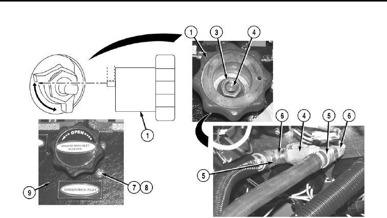
Stop on valve handle is positioned between 90 degree indent on valve.
Note position of valve handle on valve prior to removal to ensure proper installation.
3.
Remove locknut (3) and valve handle (1) from valve (4). Discard locknut.
4.
Open pump operator's panel housing (WP 0325).
NOTE
Tag and mark hoses prior to removal to ensure proper installation.
5.
Remove two hoses (5) from elbows (6).
6.
Remove two screws (7), washers (8), and valve (4) from pump panel (9).
7.
Remove two elbows (6) from valve (4).
END OF TASK
0278-2

