DRAFT
TM 5-4210-249-13&P-2
0175
TFFT04316
Step 9.
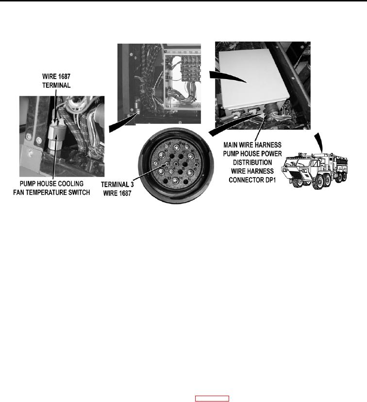
Disconnect main wire harness pump house power distribution wire harness connector
DP1. Check for continuity across main wire harness wire 1687 (brown) from main wire
harness pump house power distribution wire harness connector DP1, terminal 3 to
pump house cooling fan temperature switch, terminal.
a.
If there is continuity, repair wire 1687 in pump house power distribution
wire harness if repairable (TM 9-2320-325-14&P), or replace pump
house power distribution wire harness and block (WP 0457).
b.
If there is no continuity, repair wire 1687 in main wire harness if
repairable (TM 9-2320-325-14&P), or replace main wire
harness (WP 0455).
Step 10.
Turn battery disconnect switch to ON position (WP 0007). Start water pump
engine (WP 0022). Check if water pump engine pressure governor control
illuminates (WP 0004).
If water pump engine pressure governor control does not illuminate,
troubleshoot Water Pump Engine Pressure Governor Control Panel Does
Not Operate Properly (WP 0146).
0175-7

