DRAFT
TM 5-4210-249-13&P-2
0173
MALFUNCTION
TEST OR INSPECTION
CORRECTIVE ACTION
TFFT04739
Step 31.
Turn battery disconnect switch to OFF position (WP 0007). Remove and install
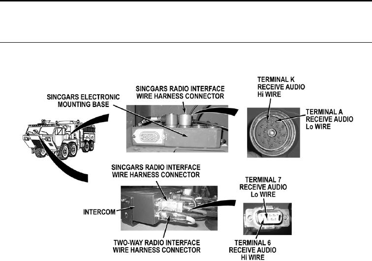
SINCGARS radio and two-way radio interface wire harness connectors RADIO B and
RADIO A on original positions. Remove SINCGARS receiver transmitter and power
adapter from electronic mounting base (TM 11-5820-890-10). Disconnect SINCGARS
radio interface wire harness connectors from electronic mounting base and intercom
(WP 0462). With a lead test set, check for continuity across SINCGARS radio interface
wire harness receive audio Lo wire (violet) from intercom connector, terminal 7 to
SINCGARS radio interface wire harness connector, terminal A.
If there is no continuity, repair receive audio Lo wire if repairable
(TM 9-2320-325-14&P), or replace SINCGARS radio interface wire harness
(WP 0462).
Step 32.
Check for continuity across SINCGARS radio interface wire harness receive audio Hi
wire (blue) from intercom connector, terminal 6 to SINCGARS radio connector,
terminal K.
a.
If there is continuity, fault is in SINCGARS electronic mounting base,
power adapter, or receiver transmitter. Notify Supervisor.
b.
If there is no continuity, repair receive audio Hi wire if repairable
(TM 9-2320-325-14&P), or replace SINCGARS radio interface wire
harness (WP 0462).
0173-21

