
DRAFT
TM 5-4210-249-13&P-1
0004
- - - - - - - - - - - - - - - - - - - - - - - - - - - - - - - - - - - - -
TFFT00943P
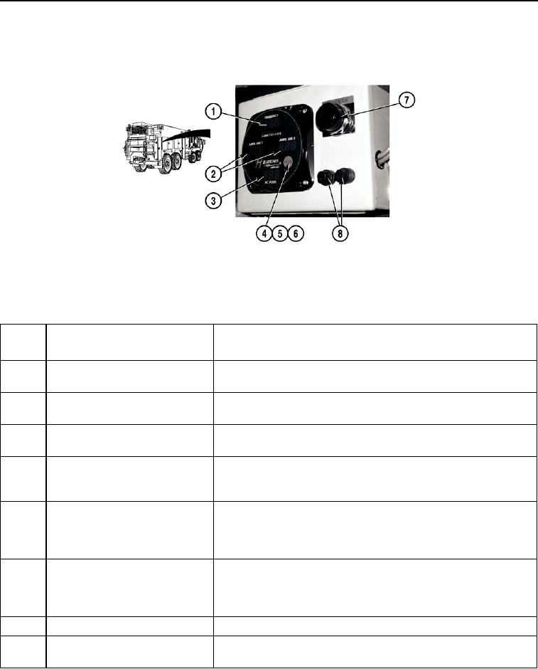
Figure 26. Hydraulic Generator Display.
- - - - - - - - - - - - - - - - - - - - - - - - - - - - - - - - - - - - -
Key
Control or Indicator
Function
Fig. 26
1
FREQUENCY LED Display
Displays generator output frequency in Hz. Range: 0 to 99.9 Hz in
one-tenth Hz increments.
2
AMPS LINE 1 and AMPS LINE 2
Displays amperage for each of two generator output lines. Range:
LED Display
0 to 150 in one-ampere increments.
3
AC VOLTS LED Display
Displays generator output voltage. Range: 0 to 300 VAC in one-
volt increments.
4
MODE Button
Allows user to switch sequentially through STANDARD display
mode, OPERATIONAL HOURS display mode and ENGINE OIL
TEMPERATURE display mode.
5
OPERATIONAL HOURS Display
Displays "HR" in the "FREQUENCY" LED panel and total
Mode
generator operating hours in the "AMPS LINE 1" and "AMPS LINE
2" LED panels. Range: 0 to 99999.9 hours in one-tenth hour
increments.
6
ENGINE OIL TEMPERATURE
Displays "OIL" in the "FREQUENCY" LED panel and engine oil
Display Mode
temperature in the "AMPS LINE 1" LED panel. The "AMPS LINE
2" LED panel displays "F." Range: 0 to 230F in one-degree
increments.
7
POWER ON Light
Illuminates when generator is engaged.
8
Fuses
Protect against circuit overload by interrupting current flow if draw
is above the circuit limit.
END OF WORK PACKAGE
0004-33/(34 blank)