Order this information in Print

Order this information on CD-ROM

Download in PDF Format


Click here to make tpub.com your Home Page

Page Title: Installation
Back | Up | Next

Click here for a printable version

Google


Web
www.tpub.com

Home


Information Categories
.... Administration
Advancement
Aerographer
Automotive
Aviation
Combat
Construction
Diving
Draftsman
Engineering
Electronics
Food and Cooking
Math
Medical
Music
Nuclear Fundamentals
Photography
Religion
USMC
   
Products
  Educational CD-ROM's
Printed Manuals
Downloadable Books


TM 5-4210-233-14&P-1 5-28.  DDEC ELECTRONIC CONTROL MODULE AND SENORS - Continued 
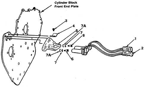
(b)  Remove the SRS/TRS retaining screw (3) and clip (4). (c)   If removal of bracket (5) is required remove two screws (6) and washers (7 and 7A). (2)   Installation. (a)   Install the sensors assembly using retaining clip (4) and screw (3). (b)   Connect the locking tangs on the SRS connector (1) and on the TRS connector (2). (3)   Adjustment. Refer to SRS/TRS Adjustment Procedures in para 6-28. e. Follow-on Maintenance. (1)   Install driver side air intake (see para 5-1 1). (2)   Install driver side turbo pipe (see para 5-23). (3)   Install engine cover (see para 4-127). (4)    Connect batteries (see para 4-114). 5-188

Privacy Statement - Press Release - Copyright Information. - Contact Us - Support Integrated Publishing

Integrated Publishing, Inc. - A (SDVOSB) Service Disabled Veteran Owned Small Business