|
| |
TM 5-4210-233-14&P-1
5-28. DDEC ELECTRONIC CONTROL MODULE AND SENSORS - Continued
(3)
Installation.
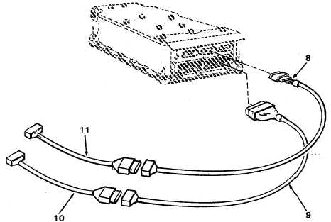
(a) Connect wiring harness (10) to electronic control unit in cab. Install rear end of harness at rear of
cab. Connect wiring harness (9) to wiring harness (1 0) at cab wall and to control module on engine.
(b) Connect wiring harness (11) to electronic control unit in cab and install rear end of harness at rear of
cab. Connect wiring harness (8) to wiring harness (11) at rear of cab and to control module on
engine.
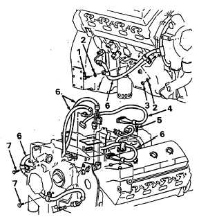
(c) Connect wiring harness (4) to control
module on top of engine. Connect other
end of harness to right bank cylinder
head.
Feed
harness
wires
through
opening in cylinder head. Check tags on
harness wires and connect wires to
engine brake retarder and to fuel
injectors.
(d) Connect wiring harness (6) to sensors on
engine. Position wiring harness (6) on
engine as shown. Connect connector on
wiring harness (6) to control module on
top of engine.
(e) Secure clamps on harness to engine
with screws (1, 5 and 7), lockwashers (2)
and nut (3).
(f)
Install clamps and tie wraps to secure
wiring harnesses.
5-184
|


