|
| |
TM 5-4210-233-14&P-1
5-18. ALTERNATOR - Continued
(21)
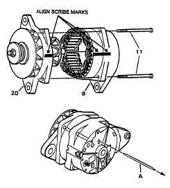
Install drive end frame (9), with
rotor shaft through bearing in
stator frame (20). Align match-
marks when installing stator
frame. Remove tape from stator
frame bearing.
(22)
Brushes must be pinned in
retracted position to allow slip
rings to enter frame. Brush pin (A)
(Item 93, Section III, Appendix B)
must extend through rotor housing
to allow removal.
(23)
Install thru bolts (11) in frames. Tighten thru bolts
to a torque of 50 lb in. (5.5 N.m).
(24)
Remove brush pin (A) from assembled atemator.
(25)
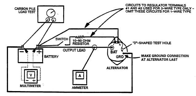
Mount alternator in a suitable test stand. A 12 volt fully charged battery should be available. Install
alternator in a test installation and make electrical connections as shown below with carbon pile
turned off.
5-107
|