|
| |
TM 5-4210-233-14&P-1
5-18. ALTERNATOR-Continued
(16)
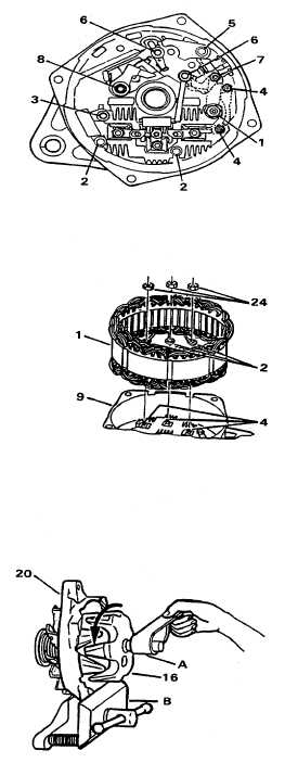
Torque screws and nuts as follows.
(a) Outside terminal nut (1) -50 lb in. (5.5
N·m).
(b) Rectifier bridge screws (2)-25 lb in.
(2.8 N·m).
(c) Capacitor screw (3)-22 lb in. (2.5
N·m).
(d) Relay and inside terminal nuts (4) -22
lb in. (2.5 N·m). It may be necessary
to hold terminal on outside while
tightening.
(e) Regulator mounting screw (grounding)
(5)-20 lb in. (2.2 N·m).
(f)
Regulator attaching screws (6)-20 lb
in. (2.2 N·m).
(g) Regulator nut (7)-22 lb in. (2.5 N·m).
(h) Brush holder pivot screw (8)-20 lb in.
(2.2 N·m).
(17)
Install outside washer, lock washer and
nut on outside stud.
(18)
Install stator (1) in frame (9) with phase
leads (2) over studs (4) on rectifier
bridge.
(19)
Install nuts (24) on studs to secure
stator leads. Tighten nuts to a torque
of 22 lb in. (2.5 N·m).
(20)
Clean slip rings by holding 400 grain
polishing cloth (A) (Item 63, Appendix
E) and spinning rotor (16). Place
frame (20) and rotor in a vise (B).
5-106
|