|
| |
TM 5-4210-233-14&P-1
5-18. ALTERNATOR-Continued
c.
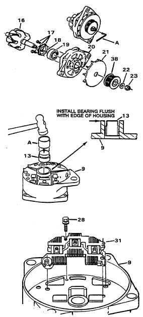
Assembly.
(1)
Install drive end bearing (19) in bore of
frame (20). Install retaining plate (18)
and secure with three screws (17).
Tighten screws to a torque of 26 lb in.
(3.0 N·m).
(2)
Install shaft of rotor (16) through
bearing (19).
(3)
Install fan (21) and pulley (38) on rotor
shaft. Secure pulley with washer (22)
and nut (23). Hold shaft with a hex
Allen wrench (A) and tighten nut to a
torque of 75 lb ft (1 00 N·m).
(4)
Install bushing (13) in bore of stator
frame (9). Use a tube or suitable driver
(A) slightly less in diameter than bore
of the frame. Drive bushing from
outside of frame until end of bearing is
flush with outside lip of frame. Cover
opening for bushing with a piece of
tape to prevent dirt from entering
during remainder of assembly
procedure.
(5)
Install rectifier bridge (31) in stator
frame (9). Install one screw (28) and
tighten finger tight.
5-103
|