|
| |
TM 5-4210-233-14&P-1
5-18. ALTERNATOR-Continued
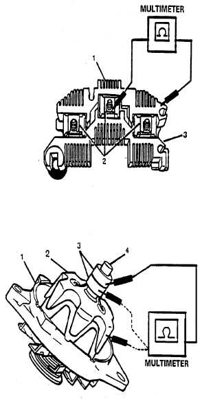
(4)
Check rectifier bridge with a
multimeter.
(a) Place negative lead on grounded heat
sink (1).
(b) Touch positive lead firmly to metal
diode clips (2) that surround the studs.
All three readings should be the same
and indicate open circuits. Switch
leads and repeat test. All three
readings should indicate continuity.
(c) If all readings are correct the rectifier
bridge is good. If any reading is
incorrect an open or shorted diode is
indicated and bridge should be
replaced.
(5)
Inspect bearing and bushing for wear
and damage.
(6)
Check connectors for bent, cracked
and damaged condition.
(7)
Use a multimeter to check rotor field
resistance.
(a) Place leads on the two slip rings (3).
Meter should read 2.2 to 3.1 ohms. If
reading is not within specifications,
replace rotor.
(b) Check for a grounded field by touching
one lead to slip ring (3) and one lead to
rotor frame (2) or rotor shaft (4).
(c) Reading should be infinite (open) to
show that field is not grounded. If field
is grounded, replace rotor.
(8)
Replace all damaged or unserviceable
parts.
5-102
|