|
| |
TM 5-4210-233-14&P-1
5-14. STARTER REPAIR AND TESTING- Continued
c.
Testing.
NOTE
Start testing with brush holder located directly over ground
terminal.
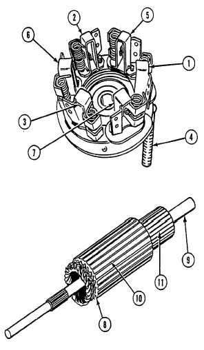
(1)
Test brush holders (1, 2, and 3) one at
a time. Place red (+) lead on ground
terminal (4) and black (-) lead on
ground terminal (4) and black (-) lead
on each brush holder. Multimeter
needle must move.
(2)
Test brush holders (5, 6, and 7) one at
a time. Place red (+) lead on ground
terminal (4) and black (-) lead on each
brush holder. Multimeter needle must
not move.
(3)
Test armature (8). Place red (+) lead
on end of shaft (9). Place black (-)
lead on each metal strip (10) around
large part of armature. Multimeter
needle must move to zero.
(4)
Place red (+) lead on end of shaft (9).
Place black (-) lead on each
commutator strip (11). Multimeter
needle must not move.
5-76
|