|
| |
TM 5-4210-233-14&P-1
4-219. MITER BOX - Continued
d.
Assembly.
CAUTION
Support inner races of ball bearings (13) when
pressing shafts (12) into them to prevent
damaging bearings.
(1)
Press shafts (12) into ball bearings (13).
(2)
Insert shafts (12) and bearings (13) into
housings (3) and press bevel gears (11)
onto shafts, aligning timing marks on shafts
and gears. Press gears on until spring pin
holes in shaft and gear are aligned.
(3)
Rotate bevel gears (11) to align spring pin
holes with grease fitting and relief fitting holes.
(4)
Insert spring pins (10) into miter gears (11) and use pin punch to drive pins in until flush with gear
hubs.
(5)
Use a spanner wrench to install two bearing retaining nuts (7), tighten till snug.
CAUTION
If same shaft (1 2) and bevel gear (11) assemblies are
reused, use same shims (4) as were removed to maintain
correct backlash of bevel gears.
(6)
Press in two new oil seals (6) until they seat against bearing retaining nuts (7).
(7)
Use a drift pin and hammer to drive locking pins (5) into housings (3) to secure bearing retaining
nuts (7) and seals (6).
(8)
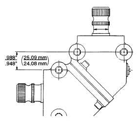
Install shims (4) between two 900 miter housings (3). Thickness of shim pack must be adjusted to
maintain .948" to .988" (25.09 to 24.08 mm) between housings (see illustration).
(9)
Install four screws (1) and lock washers (2) to assemble 900 miter boxes (3) together. Torque
screws to 35 ft Ibs (47.5 N.m).
(10)
With one shaft restrained, total backlash measured at the other shaft to be less than or equal to
0.010 inches (.254 mm) when measured with a dial indicator at a point 2.00 inches (50.8 mm)
from center of the shaft. This equates to 0.10 inches (2.54 mm) movement on a 20 inch (508
mm) steering wheel.
(11)
Install relief fitting (8) and grease fitting (9) in housings (3).
4-539
|